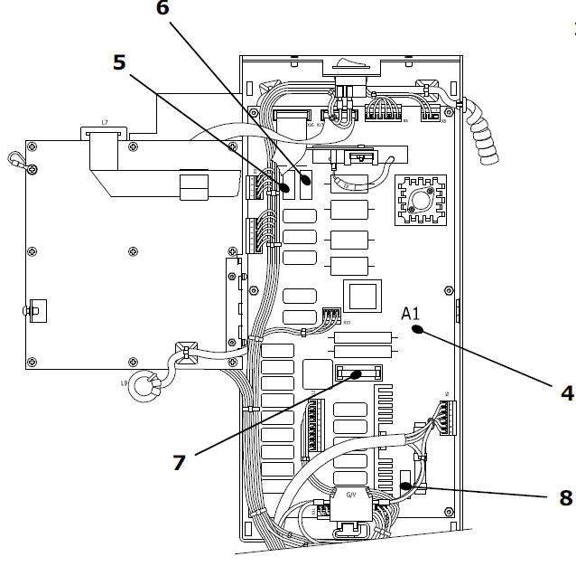
First step is to check the 4 fuses on the A1 power board #5, #6, #7, #8.
Second step is to determined if the tube head is emitting radiation.
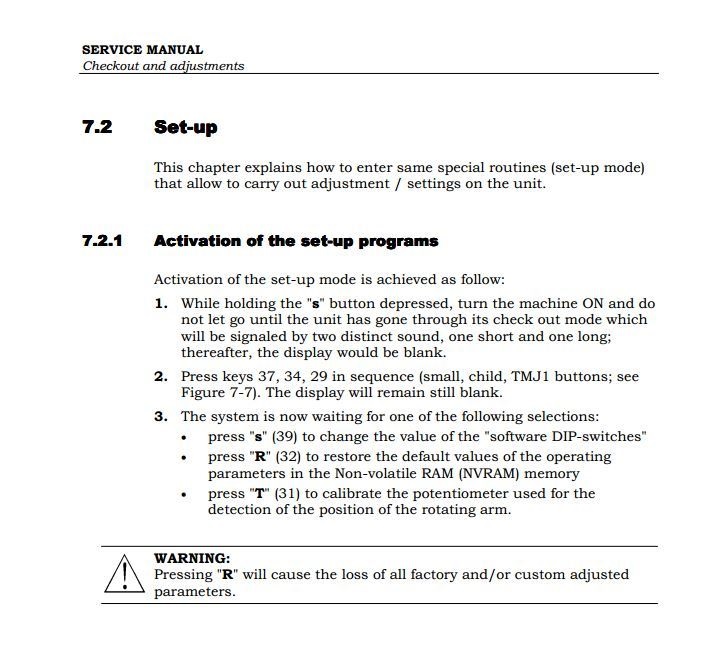
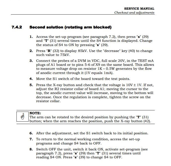
The first thing to do is place the rotation arm in stationary position so that you can expose without the arm rotating. To do this I attached a series of instructions from the service manual. You have to enter setup mode and turn S4 on.
Once you are able to expose with the Tube head stationary you should proceed.
*Note* commonly you should be able to hear the tube exposing by hearing a hissing sound from the tube wile exposing but the real way to determine if there is radiation is by placing a florescent screen in the path of the xray beam and turning off the light, standing behind the tube and exposing you should see a green light glowing on the florescent screen. Please keep in mind the room should be dark in order to notice he xray on the screen.
Once you have determined there is no xray the next step is to check the voltage reaching the tube wile pressing the exposure button. Above the tube there is a relay that is supplied voltage through a harness that goes through the rotation arm up to the top of the unit.
Please keep in mind to make sure all connections in the back of the column are connected firmly .
(I also attached a diagram of how the voltage flows from X9 connection on power board to tubehade, X9 feeds X7 cable that goes under chin rest, on A3 board then A3 board feeds harness going up to tube head)
The voltage that you should read from that harness is as follows
Brown and Blue wire should read between 170V AC and 235V AC (depending on the kv)
Blue and white wires should be 170V AC or higher
if this is not the case from the harness reaching the tube you should trouble shoot from the Powerboard A1, connection X9 , you will notice this connection is where the voltage is outputting. if by checking for voltage on the X9 connectors you do not get the adequate Voltage, you probably have an A1 failure. some of the procedures below should be helpful as well.
- disconnected the X7 tubehead connector for check the voltage
- connected the X9 connector and check the tubehead voltage when take the exposure (brown and blue wires) pins 1-2 of X9 : 235v AC 85kV – 220v AC 80kV – 210v AC 75kV – 195v AC 70kV – 180v AC 65kV – 170v AC 60kV
- connected the X9 connector and check the filament voltage : must be 170v AC when take the exposure (blue and white wires) pins 2-3 of X9
- connected the X7 connector for check the voltage with the tubehead .
- adjusting the output current mA with R2 filament : connect the probes of DVM in the TEST mA plugs of A1 board or pins 5-6 of X9 ( green and red wires ) and check thetubehead mA when take the exposure : must be 10v DC (1v = 1mA) with 75 kV
.png)
|
Rate this Topic:
|
|||
|